- CYPE >
- english >
- products >
- foundations modules >
- Footing analysis and design
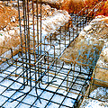

Using the Footings module, CYPECAD and CYPE 3D can design foundations resolved using rigid reinforced concrete footings or rigid mass concrete footings. These may be single column or shear wall footings or combined footings with several columns and/or shear walls bearing on them, their arrangement left to the user’s choice. This module also designs strap and tie beams between footings, and in the case of CYPECAD, strip footings below walls.
General features of the Footings module
The tools required to introduce foundations composed of footings are located at:
- CYPECAD: Foundation menu within the Beam Definition or Results tab
- CYPE 3D: Foundation elements menu within the Foundation tab
Using the Footings module, both programs allow for the design of reinforced or mass concrete footings. The may be tapered or have constant depth, and may be square, rectangular, centred or eccentric (depending on the user selection and the forces acting on the footing).


In CYPECAD and CYPE 3D it is possible to select several columns and shear walls to assign them to a common footing.
Together with the Footings module, it is possible to acquire another module which complements it by offering greater features in footing design. This is the Advanced calculation of surface foundations module, which allows CYPECAD and CYPE 3D to design foundations with footings that include geometrical trims and CYPECAD to design foundations with strap and tie beam intersections.
Automatic generation of footings and strap and tie beams
In CYPECAD, the Footings module allows for footings and required strap beams to be introduced automatically with initial dimensions before proceeding with their design. The program deduces which footings are to be introduced as corner, edge and centred footings and automatically provides the strap beams required to balance out the load of the eccentric footings. All the user must do is indicate the vision angle and vision distance so the program can detect the column layout of the structure.

The automatic footing and strap beam generation may be of great use for those structures containing a large number of columns, as it avoids having to introduce the footings and strap beams one by one. The user can modify any of the foundation elements he/she deems has bee generated inadequately later on.
The automatic footing generation in CYPE 3D is different. Here, the program generates all the footings as centred footings and places tie beams between the columns making up the perimeter, as this is what is usually done for warehouse foundations. As in the case of CYPECAD, the user may manually select the type of footing to be provided at each column.

Wall foundations designed by CYPECAD can be with external fixity (strip footing below the wall) or without external fixity (foundation beam). If the foundation is defined as a strip footing (With external fixity), the Footings module begins to design the footing as of a set of minimum dimensions, as it does with column footings. If the wall footing is eccentric (with an overhang only to one side, for example) the strap beams joining the footing to the internal columns will be designed to balance the load of the footing.
Once the structure has been analysed and designed, the user can edit any footing so to view its dimensions and reinforcement.

The footings editor also allows the user to change the type of footing, modify its dimensions and reinforcement, and even change the direction of growth of the footing. Once the specifications have been introduced by the user, the editor can check to see whether the footing complies with the modifications that have been introduced or design the footing. The design process consists of three options:
- Complete
The footing is designed taking into account the changes carried out by the user regarding the footing, materials and growth options. Any dimension or reinforcement changes that have been introduced are not taken into account. - Minimum dimensions
The program checks the footing that has been defined with dimensions provided by the user, taking into account any material changes that may have been introduced. If necessary, the program increases the dimensions of the footing in accordance with the selected type and introduced design options. The reinforcement is also designed. - Redesign
The program redesigns the reinforcement and checks the footing without modifying its dimensions.
The 2011 version of the program has brought about changes in how the forces are calculated for foundations that have been defined as “with external fixity”, applicable to both footings and pile caps as well as their strap and tie beams.
The current analysis may differ when compared to that of previous versions. Now, once the support reactions of the supporting elements (columns, shear walls and walls) of the structure have been obtained, a model is created of all the foundation elements “with external fixity” and their beams, represented by its stiffness matrix. The stiffness matrix, together with the loadcases defined as actions on the foundations (obtained reactions), is resolved using frontal methods to obtain the displacements and forces for all the elements, and so, the stiffnesses of all the elements intervene and interact with each other.
Iterations in the design process
The design process is iterative and starts off using the initial dimensions of each element. During the first iteration, the following considerations are established to determine the stiffness and fixity of each type of element:
- Pad footing or pile cap
It is taken as being a rigid solid with a central support, whose fixity in each direction can consist of a hinged support if it is reached by a strap beam or a fixed support if it is reached by a tie beam or if no beam reaches it.
- Strip footing below wall
It is defined as a rigid solid with a central support which, in the transverse direction, is considered to be hinged if strap beams and/or other walls reach it, and, fixed in the longitudinal direction.
- Tie beam
It is taken as being a bar with the stated dimensions and with hinged ends reaching the axis that passes through the centre of the element they are tying. - Strap beam
It is taken as being a beam with the stated dimensions. Its ends are fixed to the edge of the element it is balancing for the following cases:
- Edge and corner footings, and for one or two-pile pile caps, in the directions that require balancing.
- When the user marks the balancing action manually.
Strap beam ends are hinged for the following cases:
- Centred footings or pile caps with three or more piles.
- Edge and corner footings, and for one or two-pile pile caps, in the directions that do not require balancing
- When the user deactivates the manual balancing action.
Therefore, the end fixity can be modified by the user and, in a similar way as what occurs with strap beams, the ends reach the axis that passes through the centre of the element which it joins.
- Perimeter walls and strap beams reaching a transverse strip footing below a wall
This element combination is a special case, although common. It may be seen in the figure below.

Transverse walls (4) and (5) have a large stiffness compared to beams (1), (2) and (3). Therefore their effect is much greater than that of the beams. Hence, a simplification has been carried out, so the balancing effect is shared equally amongst all the transverse elements that reach the footing. This has been done by using the mean stiffness of all the strap beams and assigning this stiffness to all the elements they balance, including the walls, and so all the elements contribute in a balanced and equal way.
To obtain a more precise analysis, the soil – structure interaction should be considered as well as having an adequate soil model. However, due to the complexity of this analysis, it seems reasonable to use the aforementioned simplified analysis, as the footing is also considered to be rigid and does not receive torsional forces.
The number of iterations carried out by the program depends on the option selected by the user:
- Minimum dimensions
Once the first iteration has been carried out, the footings and pile caps are designed with the forces that have been obtained. A second iteration is undertaken and the elements are redesigned, including the beams. Using the geometry from this last iteration, a final design is carried out and all the elements are checked to see if any fail.
- Complete design
After the first iteration, the program continues iterating and tries to provide results so that none of the elements fail, which it will do unless the permitted maximum design limits for each element are reached, in which case, some will fail.
CYPE 3D modules:
CYPECAD modules:
- Steel columns
- Steel beams
- Joist floor slabs (generic concrete joists)
- Joist floor slabs (in-situ, precast and steel)
- Timber joist floor slabs
- Waffle slabs
- Flat slabs
- Punching shear verification (Also operates as an independent program)
- Composite slabs
- Hollow core slabs
- Post-tensioned concrete slabs for buildings
- Shear walls
- Reinforced concrete walls
- Plane stress walls
- Stairs
- Mat foundations and foundation beams
- Concrete block walls
- Interaction of the structure with the construction elements
- Automatic job introduction: DXF, DWG and CAD/BIM models
- Collective protection systems
Modules common to CYPECAD and CYPE 3D:
- Concrete columns
- Composite steel and concrete columns
- Concrete beams
- Timber sections
- Pile caps (includes strap and tie beams)
- Baseplates
- Footings (pad and strip) (includes strap and tie beams)
- Advanced design of surface foundations
- Fire resistance check
- Parallel analysis with two multiprocessors
- Parallel analysis with up to eight processors
- Joints I. Welded. Warehouses with rolled and welded steel I sections
- Joints II. Bolted. Warehouses with rolled and welded steel I sections
- Joints III. Welded. Building frames with rolled and welded steel I sections
- Joints IV. Bolted. Building frames with rolled and welded steel I sections
- Joints V. Flat trusses with hollow structural sections
- Export to Tekla
Tel. USA (+1) 202 569 8902 // UK (+44) 20 3608 1448 // Spain (+34) 965 922 550 - Fax (+34) 965 124 950